
TL;DR — Japanese electronics manufacturers ordering cold-rolled stainless steel strips from China for spring clip and connector terminal stamping enforce five dimensional and metallurgical checks that go beyond the ASTM A240 or JIS G 4305 standard minimums. The most common batch rejection I see from Japanese QA teams at the incoming inspection stage is hardness consistency — a 1/4H strip specified at HV 250–310 must not have a spread wider than ±15 HV across the coil length (the standard HV 60 spread is considered too wide for a terminal contact spring that requires a preload force repeatability of ±5%). Surface roughness must be below Ra 0.5 μm on the contact side of the terminal strip, and thickness tolerance must be held to ±0.03 mm for the 0.3 mm nominal gauge — a variation of 0.05 mm in strip thickness produces a 0.3 mm variation in the formed spring clip’s free height, which shifts the contact pressure by 1.2–1.5 N from the specified value. This article covers the five inspection parameters that matter when a Japanese electronics OEM places a repeat order for cold-rolled stainless steel strip.
Japan’s connector and terminal manufacturing industry — companies such as JAE (Japan Aviation Electronics), Hirose Electric, and Yazaki’s electronics division — consumes thousands of tonnes of precision cold-rolled stainless steel strip per year for stamped components: spring clips that retain the mating connector half (typically 0.2–0.4 mm thick, 1/2H temper, 301 or 304 grade), and signal or power terminals 0.15–0.30 mm thick in 1/4H temper. The strip enters the stamping press at 50–200 m/min, producing 50,000–200,000 terminals per hour through a progressive die with tolerance requirements measured in micrometres. A strip that fails the incoming inspection at a Japanese electronics factory is returned to the supplier at the supplier’s cost, plus a production line downtime claim of ¥200,000–¥500,000 per hour for the idle stamping press. We supply cold-rolled stainless steel strip to this market, and this article covers the five checks a Japanese QA engineer performs on every incoming coil. For our cold rolling production range, see the cold-rolled stainless steel product page. For the process capability in precision strip manufacturing, visit the precision stainless steel strip category.
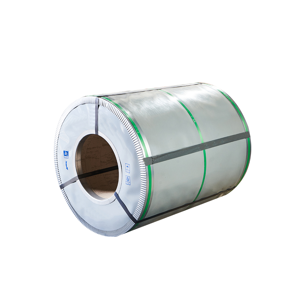
Hardness Consistency — Why ±15 HV Matters for a Contact Spring
Japanese electronics manufacturers specify the temper of cold-rolled stainless steel strip per two standards working in parallel: JIS G 4313 (cold-rolled stainless steel strips for springs) and the ASTM A240/A480 specification for the equivalent temper designations. For a 1/4H strip in 304 stainless steel, the hardness range per JIS G 4313 is HV 250–310 (a 60-point spread). For a 1/2H strip in 301 stainless steel, the range is HV 310–370 (also 60 points). The standard is a hardness range for the mill’s production — it covers the normal process variation of the annealing furnace temperature (±10°C across the strip width in a continuous annealing furnace) and the cold-rolling reduction variation (±2% in the final pass at the Sendzimir mill). But for the Japanese terminal manufacturer, a 60-point hardness spread is too wide for a terminal that must deliver a consistent contact force across 500,000 stampings.
The contact force of a spring clip terminal is proportional to the yield strength of the strip at the formed bend radius. For a 0.3 mm thick 1/2H 301 stainless steel clip bent at a 0.3 mm inside radius (the R/t ratio = 1.0 — a tight bend for a spring contact), the springback angle changes by 0.5° for every 10 HV increase in the strip hardness. A 60 HV variation across the coil means the springback angle varies by 3° — the formed clip free height varies by 0.2 mm at the contact tip, and the mating force shifts from the specified 8 N to between 6.5 N and 9.5 N. The Japanese customer rejects any batch where the hardness varies by more than ±15 HV across the coil (a 30-point window). We meet this requirement by operating the rolling mill at a controlled reduction per pass and sampling hardness at five positions (left edge, left quarter, centre, right quarter, right edge) on every coil in the batch, recording the standard deviation. If the standard deviation exceeds 8 HV, the coil is downgraded to a non-precision application. The cold-rolled strip product range is shown on the cold-rolled strip page.
Surface Roughness — Ra 0.5 μm for Contact Resistance Stability
The surface roughness of the cold-rolled strip on the terminal’s contact side determines the real contact area between the terminal and the mating pin. A terminal that carries 3 A of signal current with a contact resistance of 20 mΩ requires a real contact area of at least 0.01 mm² at the nominal contact force (8 N). If the strip surface roughness is Ra 1.0 μm instead of Ra 0.5 μm, the asperities (peaks) on the surface are taller by 0.5 μm — the plastic deformation of these asperities under the contact force creates a real contact area that is 30–40% smaller, pushing the contact resistance from 20 mΩ to 30–35 mΩ. At 3 A, the power dissipation at the contact point (I²R = 9 × 0.035 = 0.315 W) in a confined connector housing without ventilation creates a local temperature rise of 15–25°C above ambient. In a 60-connector automotive engine bay harness, the cumulative heat degrades the terminal’s spring temper — the 1/2H stainless steel stress-relaxes by 10–15% at 100°C over 3,000 hours, reducing the contact force and increasing the contact resistance further in a self-reinforcing failure cycle.
The strip surface roughness depends on four factors: the work roll surface finish (ground finish Ra 0.1 μm for the final pass), the rolling oil cleanliness (a 5 μm filter system that prevents hard particles from embedding in the strip surface), the strip tension during the final pass (maintained within ±3% of the setpoint by the tension reel’s closed-loop torque control), and the annealing furnace atmosphere (a hydrogen-nitrogen reducing atmosphere at 1,050°C for 304 and 301 grades prevents carbide precipitation and surface oxidation). We measure the surface roughness at three positions across the strip width on each coil using a contact profilometer per ISO 25178. The typical Ra is 0.35–0.45 μm on the bright side and 0.45–0.55 μm on the matte side — the customer selects the side for the contact surface. For the hard precision strip production capability, see the hard precision stainless steel strip product page.
Thickness Tolerance — ±0.03 mm Controls the Free Height of the Bent Clip
Thickness tolerance in precision cold-rolled strip is specified per ASTM A480 as ±10% of the nominal gauge for widths up to 600 mm. For a 0.30 mm nominal thickness, this is ±0.030 mm. Japanese electronics manufacturers also enforce this tolerance, but they additionally measure the thickness variation across the strip width (the crown profile) and along the strip length (the gauge band variation). The crown — the thickness difference between the strip centre and the strip edge — must not exceed 0.010 mm for a 200 mm wide strip on a 0.30 mm nominal gauge. The gauge band variation — the periodic thickness variation along the length caused by the eccentricity of the Sendzimir mill’s backing bearings — must not exceed 0.005 mm over a 10-metre length.
Why this level of precision for a spring clip? A stamped spring clip bending at a 0.5 mm radius with a 0.30 mm strip thickness (R/t = 1.67) has a formed free height of 4.5 mm. If the strip thickness is 0.33 mm (the upper limit of ±0.03 mm), the springback geometry changes because the moment of inertia of the cross-section (I = b × t³ / 12) increases by (0.33/0.30)³ = 1.33 times — the formed spring is 33% stiffer in bending, and the free height of the clip increases by 0.3 mm to 4.8 mm. The mating pin insertion force changes from the specification of 8 ± 1 N to 10 ± 1.5 N — above the customer’s upper limit of 9 N. The same effect in reverse occurs if the thickness is at the lower limit of 0.27 mm. The ±0.03 mm thickness tolerance directly translates to ±0.25 N force variation in the spring clip — and the customer’s acceptance window is ±1 N. We hold the thickness to ±0.02 mm on the centre of the coil and ±0.03 mm at the edges through closed-loop automatic gauge control on the final Sendzimir mill pass. For stainless steel strip products more broadly, see the stainless steel strip category page.
Edge Burr — The Punch-and-Die Lifetime Interface
The cold-rolled strip is slit from the full-width coil into narrower strips (20–200 mm wide, depending on the terminal width and the stamping die layout) on a slitting line with rotary knives. The slitting process creates a burr at the cut edge — a raised lip of displaced material that protrudes above the strip surface by 0.02–0.15 mm depending on the knife sharpness, the slitting clearance (the gap between the upper and lower knives, set at 5–10% of the strip thickness for precision slitting), and the strip tension at the slitting recoiler. For a Japanese terminal stamping die running at 200 strokes per minute with a punch-to-die clearance of 0.020 mm (7% of 0.30 mm strip thickness), the burr on the incoming strip edge is the first thing that contacts the die surface. A burr height above 0.05 mm will gall the die surface within 50,000 strokes — the galling creates a scratch on the die land that transfers to every subsequent terminal, producing a raised ridge on the terminal surface that prevents the terminal from seating fully in the connector housing.
We control the edge burr height through a three-parameter slitting specification: the knife overlap is set at 30% of the strip thickness (0.09 mm for 0.30 mm strip), the side clearance is 8% of the strip thickness (0.024 mm), and the knife edge radius is maintained below 0.01 mm — the slitting knives are re-ground when the edge radius exceeds 0.02 mm, which happens after 30–50 tonnes of slitting per knife set. The burr height is measured with a dial indicator on the first metre and the last metre of each slit coil. A burr height exceeding 0.05 mm is removed by a deburring station (a set of spring-loaded carbide blocks that skim the burr edge by 0.03 mm from each side) at the slitting line exit. The deburring operation costs us ¥0.30 per linear metre of strip — but a die repair bill for a Japanese terminal manufacturer’s six-station progressive die is ¥150,000–¥300,000, plus the production line downtime. The deburring operation is included as standard on all precision cold-rolled strip orders for Japanese electronics customers, at no additional charge.
Packaging and Delivery — The JIT Coil Requirements
Japanese electronics terminal manufacturers operate on a just-in-time (JIT) material flow. A 500 kg coil of 0.30 × 100 mm precision cold-rolled strip with an average strip length of 2,100 m is received and placed directly on the multi-slide stamping press payoff reel — no intermediate storage, no inspection hold. The coil must be free of overlapping wrap marks (the indentation that the outer wrap makes on the inner wraps during the recoiling and handling), because an indentation of 0.02 mm depth in the surface of the strip creates a die impact loading at the stamping press — the punch encounters 0.02 mm additional resistance at that position, the press ram tilts, and the punch tip chipped edge produces a scrap terminal.
The packaging specification for coils exported to Japan includes: a steel spool (mandrel inner diameter 300 mm, outer diameter 450 mm, side flanges 150 mm diameter), the strip wound under constant tension (50 N per 10 mm of strip width — 500 N for a 100 mm wide strip), each wrap separated by a 0.10 mm polyethylene interleaf sheet to prevent wrap-to-wrap galling, the coil sealed in a vacuum-moisture barrier bag with silica gel desiccant (the stainless steel does not rust, but the interleaf paper must be kept below 10% relative humidity to prevent the paper’s organic acids from staining the strip surface during sea freight), and the coil packed in a wooden crate with a vibration-dampening foam base. The weld joint count in the coil — each coil is formed by welding multiple 5-tonne master coil strips end-to-end at the slitting line — is limited to 1 weld joint per 500 m for Japanese orders, compared to the industry standard of 1 per 300 m. The weld joint area is marked with a yellow paint stripe 30 cm before and 30 cm after the joint, and the stamping press operator is instructed to cut out and discard the weld zone at the press entry guide.
The full product range we supply for precision stamping applications is listed on the product catalogue page.
Acceptance Checklist for Japanese QA Incoming Inspection
| Check Item | Specification for Precision Strip | Measurement Method | Rejection Threshold |
|---|---|---|---|
| Hardness — 1/4H (304) | HV 250–310, spread ≤30 HV across coil | Micro-Vickers with 1 kg load, 5 positions | Spread >30 HV or any single reading outside HV 250–310 |
| Hardness — 1/2H (301) | HV 310–370, spread ≤30 HV across coil | Micro-Vickers with 1 kg load, 5 positions | Spread >30 HV or any reading outside HV 310–370 |
| Surface roughness — contact side | Ra ≤ 0.5 μm, Rz ≤ 3.5 μm | Contact profilometer per ISO 25178, 3 positions | Ra > 0.6 μm on more than one position |
| Thickness tolerance | ±0.03 mm at strip centre; ±0.05 mm at strip edge | Laser micrometer at 10 m intervals, cross-width profile at 5 points | Any reading outside ±0.03 mm at centre or ±0.05 mm at edge |
| Edge burr height | ≤0.05 mm on both cut edges | Dial indicator with surface plate — skid referenced to strip surface | Burr >0.08 mm at more than one position in 100 m |
| Weld joint count | 1 joint per 500 m of strip length maximum | Visual inspection at coil entry and exit — yellow paint mark at weld zone | 2 joints in any 500 m segment = non-conforming coil |
For the current export specifications and pricing for precision cold-rolled stainless steel strip, the hard precision strip product page includes the available temper grades and dimensional limits. For a broader understanding of stainless steel strip processing, the cold-rolled product page describes the production equipment and the process steps.
The Japanese Industrial Standards system provides the material framework — JIS G 4313 cold-rolled stainless steel strips for springs is the applicable standard for the 1/4H and 1/2H tempers used in electronic spring contact stamping. For international reference on connector testing, the SAE International connector terminal test standards specify the contact resistance measurement method and the test conditions for connector terminals used in electronic equipment.
Frequently Asked Questions
What is the typical FOB price for precision cold-rolled 304 1/4H strip to Japan?
The FOB Ningbo price for precision cold-rolled 304 stainless steel strip, 1/4H temper, 0.30 mm nominal thickness × 100 mm width, at a 5-tonne order quantity, is $3,200–$3,800 per tonne. The price for 301 1/2H strip at the same dimensions is $3,500–$4,200 per tonne — the 301 grade uses a higher nickel content (6.0–8.0% vs. 8.0–10.5% for 304, but 301 has a higher work-hardening rate that requires more passes at the rolling mill to achieve the 1/2H temper, increasing the processing cost). The price includes the deburring operation, the polyethylene interleaf packaging, the wooden crate, and the mill test certificate per JIS G 4313. The price excludes the shipping cost (sea freight from Ningbo to Yokohama: $120–$180 per tonne, 15–20 day transit) and the Japanese consumption tax (10%).
How does the nickel surcharge affect the strip price for Japanese orders?
The nickel surcharge on the LME nickel price is applied when the nickel content of the grade exceeds the base threshold (typically 6.0% for the surcharge formula). For 304 grade at 8.0–10.5% nickel content, the surcharge component accounts for 18–22% of the total strip price at the current LME nickel price of $16,000–$18,000 per tonne. For 301 grade at 6.0–8.0% nickel content, the surcharge component is 14–17% of the price. The surcharge is calculated per the alloy surcharge formula agreed in the purchase contract, typically adjusted monthly. Japanese buyers typically request a price quotation with the nickel surcharge listed as a separate line item, so the base steel cost and the surcharge are transparent for their cost accounting.
What is the minimum order quantity for precision cold-rolled strip shipped to Japan?
The MOQ for precision cold-rolled stainless steel strip per grade per dimension combination is 3 tonnes net coil weight, which is approximately 6–8 coil spools at 500 kg each depending on the strip width and thickness. For a new customer without an established quality history, the first order is 5 tonnes minimum to cover the process validation sampling (the first batch includes destructive testing at the slitting line that consumes 20–30 m of material per coil). Repeat orders from qualified customers can be 3 tonnes minimum per shipment. The lead time for a first order is 40–45 working days from the LJME contract finalisation, including the 10-day trial rolling and testing cycle before the production batch. Repeat orders are 25–30 working days because the rolling mill parameters are already pre-set for the grade-dimension combination.
How is the surface roughness measured on the strip — can the customer verify it on arrival?
The surface roughness is measured with a contact profilometer (Taylor Hobson Surtronic series or equivalent) with a 2 μm radius diamond stylus, a 0.8 mm cutoff length, and a 5.6 mm evaluation length per ISO 25178. The measurement is taken at three positions across the strip width — 10 mm from the left edge, centreline, and 10 mm from the right edge — with the strip stationary on the packing table. The customer can verify the roughness with the same instrument on arrival. The measurement is non-destructive — the stylus contact force is 0.7 mN, which does not mark the strip surface. The customer can request a roughness control strip sample (a 300 mm length from the start and the end of each coil) included in the shipment for independent laboratory verification.
Does the ±0.03 mm thickness tolerance apply to the full strip width?
The ±0.03 mm thickness tolerance applies to the central 80% of the strip width. The 10% of the width at each edge — within 10 mm of the cut edge — has a wider tolerance of ±0.05 mm because the rolling mill work roll profile (the roll crown ground into the Sendzimir mill work rolls) causes a natural thickness increase at the strip edge. For most terminal stamping operations, the terminals are stamped from the central 80% of the strip width — the edge 10% on each side is used for the stamping die’s pilot feed holes (small holes punched through the strip that the feed finger engages to index the strip through the die). The pilot hole area does not require the same thickness accuracy because it is not a functional contact surface. Japanese customers accept this tolerance zone definition.
Can the coil be supplied with a lead-in tail for automatic threading at the press?
Yes — we pre-form a lead-in tail on the end of each coil: the strip end is ground to a 30° chamfer over a 50 mm length (removing the sharp square edge that would catch on the press guide rollers), and the tail is pre-curved to the payoff reel spool diameter so the coil end feeds smoothly into the strip straightener without cockling or folding. The lead-in tail preparation adds 15 minutes per coil at our packing station and is included in the standard packaging cost. The tail end is marked with a green paint stripe 20 cm from the strip end so the press operator can identify the start coil end at a glance on the dark factory floor.
Ningbo Xinjing Stainless Steel Co., Ltd.
Precision cold-rolled stainless steel strip manufacturer — ISO 9001 certified
We specialise in precision cold-rolled stainless steel strip from 0.08 mm to 3.0 mm thickness in 3-series austenitic, 4-series ferritic, and precipitation-hardening grades. Our Sendzimir 20-high rolling mill line produces strip to JIS, ASTM, and DIN standards for electronics, automotive, and medical device stamping applications worldwide. Contact our export team for grade-specific quotations.
Post time: Jul-09-2026


